SUBLEQ - Part II
Runtime
Now that there's a small logical model of what a true SUBLEQ computer would look like, we begin to run into some limitations. Since there is no explicit "load into mem" instruction, we begin to run into trouble almost immediately, since every computation needs a few constants along the way. To sidestep this issue, we are loading a separate RAM image and a ROM image into our computer model. Tedious - for now.
Since there's no official friendly compiler for the SUBLEQ computer yet, we will have to hand-write the raw machine code for the ROM, and fill in the RAM by hand. To test this machine, a fairly complex process is not necessary, we will be doing a simple addition 02h + 0Fh. This should return a result of +17d.
Note: As I found out the hard way, the Xilinx set of simulation tools is kinda weak when it comes to loading in files into memory arrays. All memory entries must be initialized at the same time, or fuse will just ignore it. No comments can be included in the file either (!). With these caveats in mind, let's write some SUBLEQ.
Process
From Part I, remember that the SUBLEQ instruction can be broken down into three parts. a and b refer to memory locations, while c is the address of the code to jump to if (b-a) <= 0.
00: 000000 //HLT
01: 010002 //subtract mem[1] (a) from mem[0], mem[0] = -a
02: 020003 //subtract mem[2] (b) from mem[0] mem[0] =-a-b
03: 030304 //clear mem[3], goto instruction 4
04: 000305 //mem[3] (c) = 0 - (-a - b) = a + b
05: 000000 //goto 0, HLT
nn:  ....
Writing SUBLEQ-based code First, let's examine Instruction 0 and its implementation. The instruction itself is a classical HLT instruction. The memory location 0 is always defined to be zero (and must be reset to zero by convention in this design), so mem[0] - mem[0] will result in an ALU result of 0, and then jumping to instruction [0] causes the processor to loop infinitely until RST is asserted again.
Performing this simple addition requires a few more instructions than even the simplest of commercial microprocessors (but this is a hobby project, so we have none of those concerns.) To add two numbers through subtraction is simple, but requires a few more steps.
To begin, let's examine I1 (all instructions are defined in hex.) Reading left-to-right, the highest two hex digits, 01, tells the computer to load memory location 1 as operand a. The next two digits tell it to load memory location 0, hereby known as mem[0], as operand 2, and the last digits tell it to jump to I2, i.e continue onto the next instruction.
I2 is defined similarly, subtract mem[2] from memZ (which now has -17d), and then continue onto I3. I3 simply clears out mem[3] by subtracting itself from itself, and then continuing onto I4. I4 subtracts memZ from mem[3], and mem[3] is now mem[1] + mem[2]. I5 HLTs the computer.
Now to define a small RAM initialization file. For this exercise, mem[0] will be 0, mem[1] will be 02h, and mem[2] will be 0Fh. mem[3] is where we're expecting the result to be stored, since this computer has no form of I/O.
00: 00
01: 02
02: 0F
03: 00
04: 00
(RAM listing for the test program. All the other entries are zeroed out)
Testing
To test this tiny program, we create a small testbench for the schematic in Verilog:
`timescale 1ns / 1ps

module subleq_core_subleq_core_sch_tb();

// Inputs
   reg RST;
   reg CLK;

// Output

// Bidirs

// Instantiate the UUT
   subleq_core UUT (
        .RST(RST),
        .CLK(CLK)
   );
// Initialize Inputs
       initial begin
        RST = 1;
        CLK = 0;
        #100 RST = 0;
        end


    always begin
    #10 CLK = ~CLK;
    end

endmodule
and then probe the necessary signals:
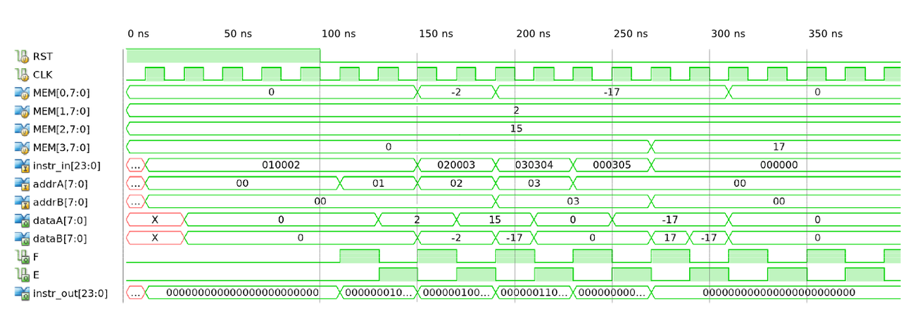
As you can see, mem[3] is now filled with the correct value of 17d, at the end of the fourth instruction cycle. After that, memZ is zeroed out (zeroing out memZ is not necessary for this one operation test, but getting into the habit saves a lot of headache.)
Attached to this post are the project files for this logical simulation plus the mem files, so it should be ready to run once you create a project in ISE Webpack (or your logic design environment of choice) and import everything in (default_probeAllTheThings is the rather-whimsically-named wave configuration file to probe all the signals necessary for this experiment.)

Comments
Comments powered by Disqus